Operating Principle
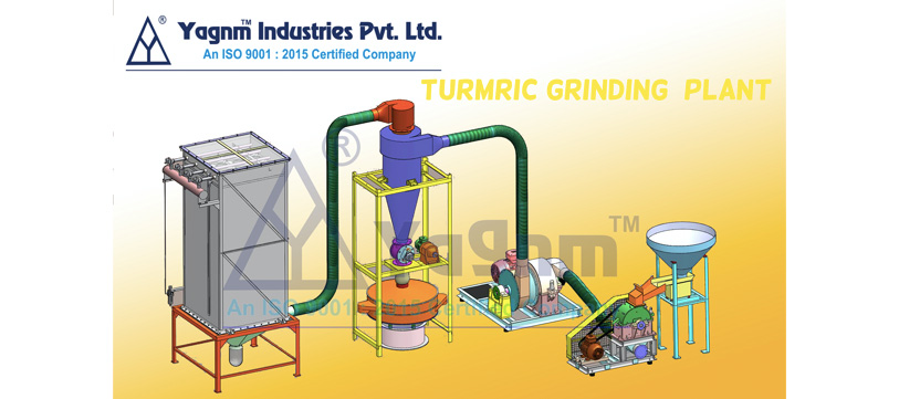
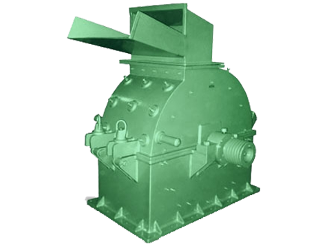
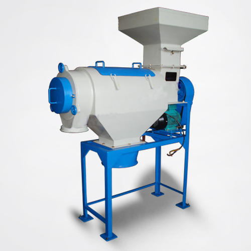
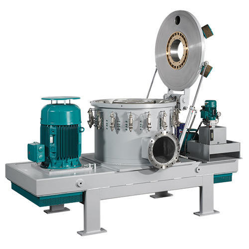
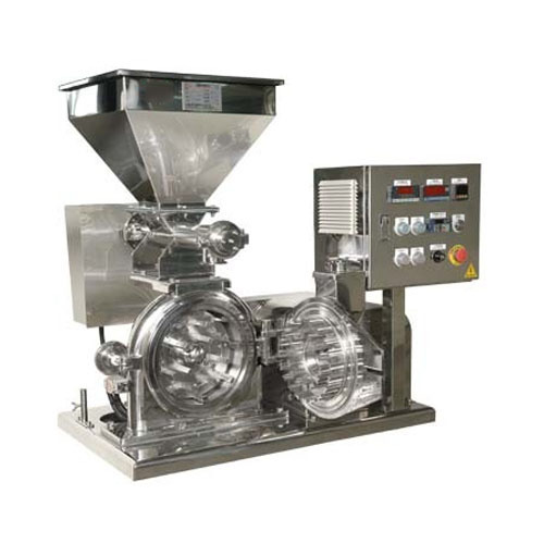
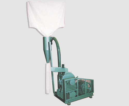
Turmeric Grinding Plant is economical unit specially designed for the Turmeric for time saving operation. The Feed hopper is suitable to store Turmeric. Below the feed hopper Vibratory Feeder is fitted. The Vibratory feeder is regulates its speed by speed controller to regulate feed of the Turmeric before entering into Turmeric Grinding Mill. The Turmeric grinding mill is technically designed to grind the Turmeric in one operation only. The grinding chamber is fitted with serrated fine liners and main shaft assembly is fitted with bar type Hammer which is fixed with carbide tip for long life of hammer.
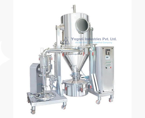
The inbuilt Air Blower is specially designed to suck all the ground Turmeric without getting high temperature. The mixture of air and ground Turmeric is delivering to cyclone separator through the air tight pipeline. The cyclone separator is efficiently separate air and ground Turmeric. The ground Turmeric is getting collected through Rotary Air Lock valve at the bottom with dust free operation. The dirty air is separated from top of the cyclone separator and passes though the pipe into the Pulse Jet Dust Collector. The Pulse Jet Dust Collector is fitted with non woven oil repellent and moisture repellent air filter which is separate the dust and clean air. The clean air is passes away into the atmosphere from the top of the Pulse jet dust collector.
Standard Supply
Turmeric Grinding Plant is complete with Feed Hopper along with Vibratory Feeder, Turmeric Grinding Mill with inbuilt air blower assembly, Mounting frame for Mill and Electric Motor, Set of Slide rail for Motor, Set of 'V' belt, Set of Anti Vibration mounting pads, Set of safety guard for drive accessories, Set of pipe line, Cyclone separator with mounting stand, Set of Rotary Air lock valve, Set of PVC Pipe line for Pulse jet dust collector and Set of Pulse Jet dust collector assembly.
Necessary But Optional Supply(At Extra Cost)
- 1. 1. Electric Motor for Mill
- 2. Electrical Panel Box with starter DOL/Star Delta & ampere meter for load indicator.
- 3. Air Compressor
| Model No. |
Rotor Dia (in mm) |
Chamber Width (in mm) |
Recommended Motor HP/RPM |
Over Dim. In Meter L*W*H |
Capacity Kg/Hr. |
|---|---|---|---|---|---|
| ASM-MS05 | 250 | 130 | 5*2880 | 3.0*2.0*3.0 | 25-30 |
| ASM-MS10 | 300 | 200 | 10*2880 | 4.0*3.0*4.0 | 50-60 |
| ASM-MS20 | 450 | 220 | 20*2880 | 5.0*4.0*4.0 | 100-125 |
| ASM-MS40 | 600 | 360 | 40*1440 | 7.5*5.0*5.0 | 200-250 |
| ASM-MS60 | 750 | 450 | 60*1440 | 10.0*7.5*5.0 | 300-400 |
| ASM-MS75 | 900 | 550 | 75*1440 | 12.5*10.0*6.0 | 500-600 |
| ASM-MS100 | 1050 | 650 | 100*1440 | 15.0*12.5*6.0 | 700-800 |
| ASM-MS125 | 1200 | 750 | 125*1440 | 18.0*15.0*6.0 | 900-1000 |
| ASM-MS150 | 1350 | 850 | 150*1440 | 20.0*18.0*8.0 | 1100-1200 |
| ASM-MS200 | 1500 | 900 | 200*1440 | 25.0*20.0*8.0 | 1400-1500 |


 WhatsApp